Monday, September 26, 2011

Cutting carefully

I needed to remove the stock shock tower braces from the shock towers, and I wanted to do so by drilling out the spot welds, but not drilling through the shock tower.  Essentially, imagine you have two pieces of sheet metal laying on top of one another, and the goal is to cut through only the top layer.  I picked up a 3/8" Double Sided Rotary Spot Weld Cutter from Harbor Freight.  This is essentially a 3/8" hole saw, but the center point is a spring-loaded adjustable pin, which depresses into a center-punch mark, and allows the "hole saw" to cut through a top level of material.  The trick, as someone joked about, was having "the hands of a surgeon."  Now, I don't by any means have the hands of a surgeon, haha, but I did work VERY slow and cautiously.  If you'd like to follow the same approach as myself, here's what tools you will need:

Hammer
Center Punch
Spot Weld Cutter (link above)
A few steel, sharp chisels (I would buy these from Harbor Freight because you'll likely destroy the blade...)
Drill
Pliers
*Optional but makes things much easier - Angle Grinder with Cutoff wheel and grinding wheel (or sandpaper disc)


Now, to start, I unbolted the braces from the firewall to the shock tower, so I was left with just the shock tower brace.  You can look closely at the brace and notice there are about 5-6 spot welds holding it on.  I used the cutoff wheel to cut off all the extra material that isn't welded.  This isn't an option if you want to keep them; it just makes it easier to get to the back side.


First things first - this will take a while!  Go very slow, doing one step at a time, and you'll probably have to switch between the different methods frequently to prevent cutting through. 


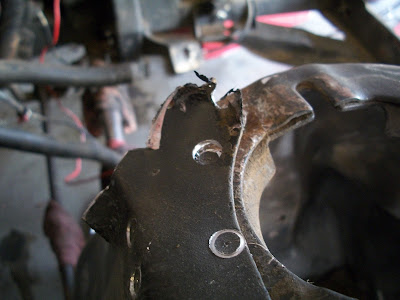
To start, hammer the center punch into the little divets (spot welds).  This will be where the drill bit is centered.


Next, place the drill bit into the drill and put the center pin into the punch location.  Accelerate the drill before pushing it into the material. These bits "walk" very easily, and you don't want to screw up the center punch park, because drilling a straight hole will become very difficult.  The approach you want to take when drilling through the material is several quick, small, pushes of the drill into the material.  Remember, the pin is spring-loaded, so that is somewhat helpful.  Don't sit on the drill and grind it down into the material because you are sure to go right through both pieces of metal.

Here's a picture of the drilling being started (bottom of image) and one that is already done (center of image).


After doing this for a few seconds, switch over to the hammer and chisel.  Place the chamfer-side against the shock tower, and chisel a bit, just to pry the two pieces of metal apart, and (very slowly) bend it upwards.  I'm only talking like 1/32" - not a lot.  Chisel around all sides of the hole you just drilled and you'll slowly see that the metal is starting to separate.  If, when doing this, you need to drill a little more, switch back, drill some, then chisel some more.  Slow and steady wins the race :-)


After a bit of this, you'll notice that the chisel will separate the cylindrical slab of "spot weld metal" from the shock tower brace - this is exactly what you're going for.  You can move onto the next spot weld, and later you can go back over this with a grinding disc or a sandpaper-disc to grind it flush with the shock tower.


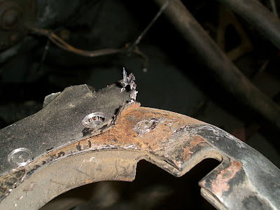
Here are the spot welds, with the shock tower brace completely cut off.


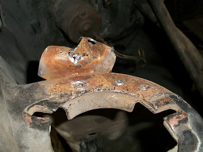
Here is how they look finished; drilled out and sanded down to the shock tower.


*******************************************

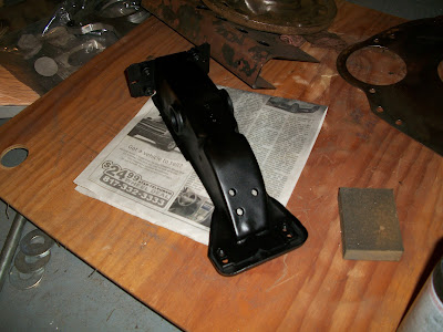
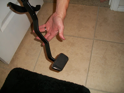
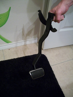
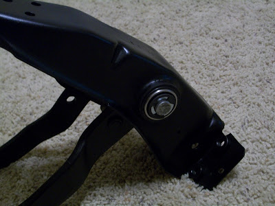
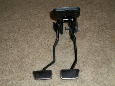
Another thing I worked on last week was getting my pedals and Pedal Support Brace all painted.  Everything has been cleaned and is ready to be installed the in car. After the support bracket was welded with the ballbearing clutch conversion kit pieces, I painted it.  I also removed the pads from the pedals and painted them as well (after sanding them down of course).  I think it turned out fantastic - here's how everything looks:


*******************************************

The last chore of the week was removing paint from the engine bay.  Someone had suggested Easy-Off Oven Cleaner, which didn't do much as far as paint removal (it did remove some, and it removed quite a bit of grease...just not what I was looking for).  So I did some research and went with a non-toxic cleaner named Citristrip.  I plan on getting some before and after pics this week to show the cleaner's progress.

Still no news on the T-5.  The guy who owns the shop that builds them has been out of the office, conveniently, every time I call.

Well that's about it for today.  Busy week ahead...

Sunday, September 18, 2011

Clutch work and T-5 Stuff

Thanks to my awesomely talented friend, Phillip, I now have the ballbearing clutch pedal conversion kit installed! 


It looks fantastic, and (though it isn't hooked up to anything right now), the feel is just sweet.  Practically no resistance at all! 

Here's a few pictures of the right, left, and bottom.  Notice in the third picture, the washers that were tacked on the inside to provide equal spacing of the brake pedal pivot.


* * * * * * * * * * * * * * * * * * * * * * * * * * * * * * * * * * * *

In addition to this, I received my T-5 adapter I bought on eBay (from a company named SMR),


and began the work on adapting the adapter to the bellhousing.  Below are the pics of the modifications necessary to adapt the 1967 inline-6 bellhousing to the T-5 adapter.

First, I installed the plate to my bellhousing using the two flathead screws on the left side of the plate.  One of the holes on the top right (the one closest to the concentric ring) needs to be transferred to the bellhousing, so I used a transfer punch to locate it.


Then I started drilling.  Unfortunately after this step, I found that I screwed up drilling the hole out (really should have started with a smaller pilot hole.  Completely my fault...  But, I created the hole and enlarged it to the correct 15/32" size.


Once that hole was done, it was time to locate the special "inline 6" bolt hole.  This hole is not transferred from the adapter - you will have to find the spot by yourself.  The reason, as seen in this thread, is due to the countersunk hole on the bottom right extending over the edge of the bellhousing.  So, someone once recommended drilling a hole in the thin part of the adapter, and putting a bolt & nut on there that is just long enough without sticking through the nut into the bellhousing.


The result (which I'll have to get more pics of later), is that the adapter is held onto the bell via 4 fasteners, one on each corner, or so.


Last bit of an update before I'm off for the night; I found out I was incorrect in putting the gasket on the axle before the axle flange...It goes on afterwards  Not a big deal, however, since I can just cut it off and put it back on the outside...perhaps use something sticky to keep it in place while attaching, and then it doesn't matter.

Next steps for the Restoration involve getting the new brake lines for the new rear end (dual exhaust kit) which is going to set me back a little more than $100.  But, at the same time.....there's a brand new 2V Converted Inline 6 head on eBay right now, and I really want it.  But dang it's expensive.

Friday, September 16, 2011

Wheel bearings on!

I bought a press yesterday afternoon, from Harbor Freight.


So I finally got to install my wheel bearings.  Sorry, but I am not paying a shop more money to press on bearings, than it costs to buy a press.  It's not even hard...nor did it take more than 10 minutes.  Anyway, off my soapbox...

It's fairly straightforward, if you want to buy a HF press and do it yourself (the 12-ton is just barely tall enough, for 65-66 axles).  The first thing you do is to make sure the axle gasket goes on first, followed by the loose axle flange (you'll see it in the pictures.  Next, with the bearing race surface clean, slide the axle bearing down the axle until it stops.  No need to jam it down tight or anything...just let it sit.  I forgot to put my axle gasket on, and had to slightly cut it to get it on there...not a big deal but annoying.

Now, turn the axle upside down and slide it onto the press so that the bearing sits against the arbor plates, like so:


Make sure the press is centered, and begin pressing down.  It would not hurt to place a thick, flat piece of metal between the press and the axle for good force distribution.  Center it as best as possible. 

Now, press down, until the bearing rests against the bearing seat (a lip that prevents it from going any farther. 

I like to turn the whole axle 180* at this point, and re-press slightly, to make sure it is evenly seated.

Next, repeat the operation with the bearing race, that should have come with your bearing. 


Once done, thoroughly go over the axle bearing and retainer to make sure there are no gaps.  You want it seated perfectly.  Here is the completed assembly:


Don't worry about the creepy noises coming from the press, by the way.  That's normal.

Now on to paint the housing!

Tuesday, September 13, 2011

Housekeeping

I got quite a few things done over the last few days, but haven't posted too much...

I removed the axle bearings and retainers.  I still don't know of any shop that will press on axle bearings for cheap, so I might just buy a press and do it myself.  Stupid overpriced shop prices...

I also finally got the front leaf spring bolt cut out.  That was one of the hardest things to "work on," on this car.  But ironically, once I got a the correct size cutoff disc (5" is minimum) and the angle grinder offset the way I wanted it, it came off with a snap.

The third thing I got finished was not really on my own; I had my brake pedal support bracket welded up with Mustang Steve's Ballbearing Clutch Pedal Conversion Kit. I can't wait to get it back tomorrow.  As a tip, we found that the large fender washers to be tacked on the inside of the support bracket do not necessarily need to be tack-welded on.  They have an ID very close to the shaft, so they will still space as they are intended. I think.   We'll see....

Hmm, I also ordered a T-5 Adapter Plate for my C4 to T-5 Swap.  It set me back $113, which wasn't too bad considering they're normally $160 + shipping.  Now all I have left is the T-5, shifter, clutch kit, and some miscellaneous parts.

The last thing I got done was cleaning up my atrocious garage.  Seriously, it was bad.  Embarrassing even...  My wonderful wonderful wife helped me clean up a ton of crap and load it on the truck to take to the dump.  After that, I had a few quarts of ATF that had leaked all over the floor from the C4, that kitty litter made quick work of.  I got a new crate to put all my bagged & tagged parts in, and swept the floor of all the dirt/grime/etc. Finally I don't feel as if I'm in a rats nest working.

Well that's all for now.  Gotta track down some things and get some more work done.

Thursday, September 1, 2011

An Auto No More

She's gone!

I've always thought "well, if things really go to heck, I can always resort back to the Auto," but that is officially out the window.  The auto is gone, and now it's just a matter of time before I can purchase a rebuilt T-5 (hopefully quickly...money burns around here).

With the ATF-sieve sold, I finally have enough money freed up to purchase the T-5, which will leave me with approximately $406 to go on my inline 6 T-5 Conversion.  That $406 basically comprises of: Shifter Base, Transmission Mount, Clutch Kit, Throwout Bearing, Roller Pilot Bearing, Shifter, Shifter Boot, Shifter Boot Trim, and a Speedometer Gear.  Note that the Shifter alone is $150, so perhaps I can cut a few bucks off by going with a lesser model or a used one...I'm not sure.

Oh, in other news, there's about umpteen jillion gallons of Automatic Transmission Fluid all over my garage right now.  Joy, joy.  Time to buy some Kitty Litter.